The first one is a manual rack, however .... This is the best I can do mate,
8. Steering
8.1. Specifications
GENERAL INFORMATION
Steering Pinion type with travmobezopasnoy the steering column. Rijk
installed in the hull of the steering equipment. Steering traction connected to
rail through the joints, covered with rubber cover. By the levers of steering traction
align through ball joints. Depending on the complete set at
the car can be installed assisted steering.
A gear ratio steering:
- Free-assisted steering
20.8
- With assisted steering
17.5
The number of turns the steering wheel from lock to lock:
- Free-assisted steering
3.83
- With assisted steering
3.17
8.2. Steering draft
Withdrawal
HOW THE IMPLEMENTATION
1. Disconnects the lead from the «negative» terminals of the battery.
2. Podlozhit bars under the rear wheels.
3. Loosen the bolts fastening the wheels.
4. Lift the front of the car and set it on the anvil.
5. Remove the wheel.
6. Measure the length of external threads a ball joint 15, a speaker from the nuts
1, and write it (see fig. The steering equipment).
7. Opened nut 1 outside a ball joint 15.
8. Vypressovat outer ball joint 15 steering traction.
9. Remove the collar 5 with gryazezaschitnogo cover 6.
10. Download gryazezaschitny cover 6 with a flange 24 gear casing and
move it.
11. Opened nut 7 and noted painted face of internal pivot
4 at carving rack 8.
12. Opened an internal ball joint and remove the 4 cravings 2, or 13.
13. Guest gryazezaschitny jacket collar 5 and 6 with the steering traction.
Setting
Warning
Damaged steering traction control are not repairable and must be
replaced.
HOW THE IMPLEMENTATION
1. Adjust the length of the right steering traction 13 point 16 steering traction control,
opened nut 14. The length of the right steering thrust 13 shall be 379 mm (381
mm automatic gearbox). Tighten the lock nut 14 point 35 N m.
2. Left steering traction installed at the factory, is not regulated. When
replacing fixed adjustable traction, the length of which must be fit to the length of
old, unregulated power.
3. Tighten the nut a new steering traction point 35 N m.
4. Set the rack so that both its end out of the sump to equal
distance.
5. Browse through carefully gryazezaschitny cover 6 and at the slightest damage
to replace it.
6. Put on a new thrust steering yoke 5 and gryazezaschitny cover 6.
7. Twist inside ball joint 4 to the point made earlier by carving
rack 8, or at a distance = 70.5 mm (see fig. steering mechanism
Management).
8. Tighten the nut point 35 N m.
9. Pressed outer ball joint in the 15 lever swivel pin.
Warning
Every time you install the steering thrust to use a new nut 1
External ball joint.
10. Twist the nut 1 at length, measured before, the moment 35 N m.
11. Gryazezaschitny wear a jacket 6 to 24 flange gear casing and the other
end - to slot a rubber bushing 3.
12. Set collar 5 to 6 gryazezaschitny case.
13. Adjust the convergence front wheels (see 9.1.7).
8.3. The steering equipment
GENERAL INFORMATION
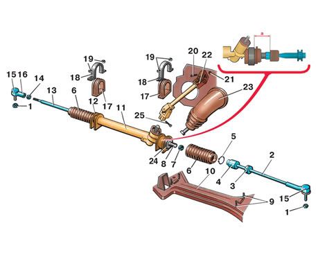
The steering equipment
1 - nut;
2 - left steering traction;
3 - rubber sleeve;
4 - inner ball joint;
5 - clamp;
6 - gryazezaschitny bag;
7 - nut;
8 - rack;
9 - bolt;
10 - beam suspension;
11 - steering mechanism
collection;
12 - place for the bracket
fixing the steering mechanism
management;
13 - right steering traction;
14 - nut;
15 - External ball joint;
16 - Right-tip steering traction;
17 - rubber pad;
18 - bracket;
19 - nut;
20 - bolt;
21 - nut;
22 - cardan shaft;
23 - gryazezaschitny bag;
24 - flange gear casing;
25 - bolt;
I - the distance «and» to install
Internal ball joint
Withdrawal
Warning
The steering equipment beyond repair and should be replaced with
damage.
HOW THE IMPLEMENTATION
1. Disconnects the lead from the «negative» terminals of the battery.
2. Podlozhit bars under the rear wheels.
3. Loosen the bolts fastening the wheels.
4. Lift the front of the car and set it on the anvil.
5. Remove the wheel.
6. Disconnects steering traction 2 and 13 of the lever swivel pin.
7. Disconnect and move up gryazezazitny cover 23.
8. Turn bolt 25.
9. Nuts to turn 19 brackets 18.
10. Remove the brackets 18.
11. Take 11 steering mechanism through a hole in the left-wing housing.
Warning
If you have any problems with removing the management mechanism, it is necessary
disconnect the steering column and raise it up to cardan joint can be
be removed from the slot leading shaft rack.
Setting
Warning
All self nuts should be replaced with new ones.
HOW THE IMPLEMENTATION
1. Set the steering mechanism 11.
2. Set the rack 8 so that it ends served by the same length
(movement of the car in a straight line).
3. Set the steering wheel so that the spokes in a horizontal
situation.
4. Set cardan joint lead slot on the shaft rack and profit
bolt 25.
5. Vyrovniyat rubber cushions 17 and to install brackets on the 18 bolts 9.
6. Twist nuts evenly on a diagonal 19-point 30 N m.
7. Connect the steering traction 2 and 13 to the levers of the swivel pin.
8. Tighten all the nuts and bolts after the installation of the car to the ground.
9. Replace the cover gryazezaschitny 23.
10. Adjust the convergence of wheels.
