The N75J K H valves cause the turbo to over boost to give the feeling of a BIGGER kick of power, for everyone not running the OEM N75 stock or mapped can you do some logs and post your results up?
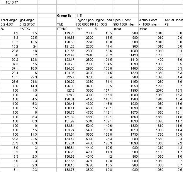
Plot of an AUM with N75C valve as you can see the boost plots are following the remap requested levels, which is correct to the mapping and is correct.
Same car same mapping BUT with the N75J fitted now over boosts to 2270Mb from the requested 2000mb... Just a quick cheat to make power, but the ecu will soon learn over time, so when you first fit the J the boost kicks hard, then over a period of time will end up where it should be. (until battery disconected or adaptions reset)
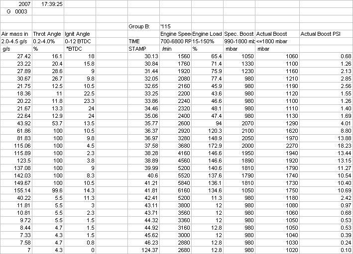
It would be cheaper and better to change the max load map from 157% to 174% in the mapping to take the requested boot to 2270mb instead of adding a and uncontrolled boost spike?
The H J K valves are designed for the K04 turbos the C F E are for the k03/s turbos.
Edit H J K designed for bigger slower spooling turbos such as the ko4, and C F E smaller quicker spooling turbos or car with high dc n75 maps)Fitting a H J K valve to a k03 turbo and ecu will induce a turbo faster spool and more over boost in the mid range, but the ecu soon adapts and pulls the boost back in to line which can be seen on the N75 logs. The H J K valves will reduce the power at the top end againback to back you can see the n75dc working harder to maintain boost. Its the feeling of a kick which the H J K valves give the smaller turbo which makes ther driver feel like the car is faster, but at the end of the day the average power it about the same, in some cases lower. The ecu is designed to meet load/boost once this load has been meet the ecu will cut the boost back via boost controller PIDS, which are there to stop boost over/under shoot oscillations (not an easy ecu to fool)
For all of you who want to understand boost pids here is a copy of a wiki page for me7 tuning.
(Just to note the
PID I is what I use to give the car the kick of boost or linear boost depending on the mapping and customers needs)
Boost PID
If your actual boost is not meeting requested boost, you may have to increase the PID I limit between 2250 and 5000 RPM for 850 and 1000mBar:
KFLDIMX - LDR I-Regulator limit
To go along with KFTARX above, there is another IAT correction that ME7.1 uses to allow the PID to add waste-gate duty cycle at elevated IATs. You may want to zero it all out:
LDIATA - LDR I-Regulator limit as a function of IAT
If you aren't using K03s, you may have to tweak the PID response. Note: this is NOT used to adjust requested boost. It is used to compensate for different waste-gate responses.
KFLDRL - Map for linearization of boost pressure = f(TV). This is the post-PID waste-gate duty correction table.
LDRQ0S - LDR PID Q0 in static operation (proportional term)
LDRQ1ST - LDR PID Q1 in static operation (integral term)
KFLDRQ2 - LDR PID Q2 (differential term)
KFLDRL can also be used to get open-loop type behavior for operation past the MAP and requested boost limit by making the output duty cycle unresponsive (flat) to uncorrected duty cycle (from the PID) at various RPM/DC points. Again, if you do this, make sure to leave DSLOFS at the stock value! This way, requested boost will always be higher than measured boost, and you will stay in open loop control.
With after market or external waste-gates flat line the map at something like 25% until your turbo should be spooled and then taper off to 10% at areas if higher load and RPM. Log requested vs. actual boost to see where you need to adjust KFLDRL to line things up. The higher your after market waste-gate spring pre-load the lower the WGDC you will need to accurately control boost.
If you don't get all of this just right, and your actual boost goes too far above requested boost (by ~200mBar), you may experience overboost throttle cut, which is ME attempting to get boost back under control by temporarily closing the throttle plate.
Alternately, if your requested boost is far too high for a given load/rpm point, you may experience positive deviation (underboost) limp mode. Many hours go into getting the boost pids correct.
IMO £90 for a valve to give that feeling is a waste of money, as its only a 5 min job to change the boost PIDs in the mapping to give the same effect and actually make more average power with out tailing off at the top end.
